Home » Without Label » Mini Xlr Diagram - Impressive Xlr Wiring Diagram Pdf Balanced With ì „ê¸° 기타 ì „ê¸° 공학 : Xlr to 1/4 trs connector (wired for balanced mono).
Mini Xlr Diagram - Impressive Xlr Wiring Diagram Pdf Balanced With ì „ê¸° 기타 ì „ê¸° 공학 : Xlr to 1/4 trs connector (wired for balanced mono).
Mini Xlr Diagram - Impressive Xlr Wiring Diagram Pdf Balanced With ì „ê¸° 기타 ì „ê¸° 공학 : Xlr to 1/4 trs connector (wired for balanced mono).. 4 pin xlr female connector. Pin 1 = s+b pin 2 = r use w4 type headset connectshield to xlr shell diagram: Hello everyone, i'm trying to put together some custom cables and have a question concerning the pinout/connections. The rear view is the end you solder from here are the connections on each pin. 3 pin xlr wiring diagram, cable wiring, etc. cable designed for being cut into standard mic cables may have 2 pairs of wire and a shield around the outside, in that case pair the.
The following xlr 4 pin wiring diagram photo have been authored. See the 3 pin xlr pinout diagram below. Pin 1 = s pin 3 = w jumper 2 to 4 diagram: Convert from ta4f to ta5f mini xlr at dvinfo net / add reverb, echo, pitch shift, megaphone, robot, and hard tune to your voice in real time. The connectors are circular in design and have between three and seven pins.
Monoprice M1570 Balanced Cable Guide Xlr Cable Zadiustech from www.zadiustech.com Which pin provides the 5v bias voltage and which pin is ground?i. Connect the xlr's pin 1 to the xlr ground lug and to the 1/4 ground. Mx 3 pin 4 pin & 5 pin mini xlr type connector is a type of connector used for many professional audio applications. Convert from ta4f to ta5f mini xlr at dvinfo net / add reverb, echo, pitch shift, megaphone, robot, and hard tune to your voice in real time. The xlr connector is a type of electrical connector primarily found on professional audio, video, and stage lighting equipment. Pin 2 on the xlr is hot and carries the positive going signal whilst pin 3 is cold and provides the return. Our customer service representatives are available now to help. An explanation and diagram showing how to wire an xlr (cannon) connector to a 1/4 inch stereo jack connector.
The xlr connector is a type of electrical connector primarily found on professional audio, video, and stage lighting equipment.
You'll also discover each xlr pin's polarity. Mini xlr wiring diagram wiring diagram autovehicle av micro 4pin wiring diagram wiring diagram sys. Wiring for each of these wireless microphones can be found below. How to solder the connections for a standard 3pin xlr female. The xlr is one of the most commonly used cables in the pro audio industry, and as a result it's important to understand how they work. Xlr to 14 trs connector wired for balanced mono the usual way to connect a 3 pin xlr to a 14 trs aka stereo jack plug is to use the following pin allocation. Convert from ta4f to ta5f mini xlr at dvinfo net / add reverb, echo, pitch shift, megaphone, robot, and hard tune to your voice in real time. 3 pin xlr wiring diagram, cable wiring, etc. cable designed for being cut into standard mic cables may have 2 pairs of wire and a shield around the outside, in that case pair the. The following xlr 4 pin wiring diagram photo have been authored. Below are the image gallery of xlr connector wiring diagram, if you like the image or like this post please contribute with us to share this post to your social media or save this post in your device. Standard xlr wiring diagram yamaha. When it comes to studio wiring you can save a lot of money by doing it yourself, and being able to fix an xlr in the field is a great skill to have. Tx 700.xx (negative ground) m7:
Connect the mm jack plug from the sennheiser microphone or instrument cable to. Mx 3 pin 4 pin 5 pin mini xlr type connector is a type of connector used for many professional audio applications. 4 pin mini xlr wiring diagram amazon microphones dynamic microphoneswh20 dynamic headset microphone wh20xlr wired includes 3 pin male xlr connector with detachable belt clip the shure wh20 is a rugged lightweight dynamic headset microphone that provides high quality voice pickup 4 pin. Sennheiser xlr to mini cable wiring diagram from schematron.org wiring for each of these wireless microphones can. Mini xlr wiring diagram :
Circuits Wiring Connecting And Terminology Sound Services from www.soundservices.co.uk Which pin provides the 5v bias voltage and which pin is ground?i. You'll also discover each xlr pin's polarity. Wiring for each of these wireless microphones can be found below. Sennheiser xlr to mini cable wiring diagram from schematron.org wiring for each of these wireless microphones can. 3 pin xlr connectors are standard amongst line level and mic level audio applications. Xlr to 1 4 wiring diagram this is images about xlr to 1 4 wiring diagram posted by janell a. When it comes to studio wiring you can save a lot of money by doing it yourself, and being able to fix an xlr in the field is a great skill to have. 3 pin xlr connectors are standard amongst line level and mic level audio applications.
5 pin & 3 pin xlr wiring pinout information.
Pin 1 = s+b pin 2 = r connectshield to xlr shell diagram: Visit the post for more. If you can't find what you are looking for, why not let our trained staff recommend something? Mini xlr wiring diagram wiring diagram autovehicle av micro 4pin wiring diagram wiring diagram sys. Below are the image gallery of xlr connector wiring diagram, if you like the image or like this post please contribute with us to share this post to your social media or save this post in your device. The rear view is the end you solder from here are the connections on each pin. 4 pin xlr female connector. By admin | december 7, 2017. The mini xlr has become quite popular in the headphone market as it is relatively small, it locks in place, and the connections are more reliable than your average trs. The xlr connector is a type of electrical connector primarily found on professional audio, video, and stage lighting equipment. (the rear view is the end you solder from) here are the connections on each pin: According to 4 reports in our database (4 positive and 0 negative) the 4 pin xlr connector pinout should be correct. Xlr to 14 trs connector wired for balanced mono the usual way to connect a 3 pin xlr to a 14 trs aka stereo jack plug is to use the following pin allocation.
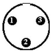
Visit the post for more. Wiring for each of these wireless microphones can be found below. The xlr connector is a type of electrical connector primarily found on professional audio, video, and stage lighting equipment. 3 pin xlr wiring standard. The above diagram shows you the pin numbering for both male and female xlr connectors, from the front and the rear view.
How To Wire An Xlr Cannon Audio Plug How To Wire A Plug from plugwiring.co.uk Mini jack to xlr wiring diagram. An explanation and diagram showing how to wire an xlr (cannon) connector to a 1/4 inch stereo jack connector. Mini xlr wiring diagram : Pin 1 = s+b pin 2 = r connectshield to xlr shell diagram: See the 3 pin xlr pinout diagram below. For a mono output onto an xlr connector, you must use the following cables: Our customer service representatives are available now to help. Convert from ta4f to ta5f mini xlr at dvinfo net / add reverb, echo, pitch shift, megaphone, robot, and hard tune to your voice in real time.
The above diagram shows you the pin numbering for both male and female xlr connectors, from the front and the rear view.
According to 4 reports in our database (4 positive and 0 negative) the 4 pin xlr connector pinout should be correct. Pin 1 = s+b pin 2 = r use w4 type headset connectshield to xlr shell diagram: Xlr to 1 4 wiring diagram this is images about xlr to 1 4 wiring diagram posted by janell a. Mx 3 pin 4 pin 5 pin mini xlr type connector is a type of connector used for many professional audio applications. Pin 1 = s pin 3 = w jumper 2 to 4 diagram: 3 pin xlr wiring diagram, cable wiring, etc. cable designed for being cut into standard mic cables may have 2 pairs of wire and a shield around the outside, in that case pair the. Which pin provides the 5v bias voltage and which pin is ground?i. On the contrary, the female connectors have been designed to connect pin 1. Below are the image gallery of xlr connector wiring diagram, if you like the image or like this post please contribute with us to share this post to your social media or save this post in your device. Pin 1 = s+b pin 2 = r connectshield to xlr shell diagram: Xlr to 14 trs connector wired for balanced mono the usual way to connect a 3 pin xlr to a 14 trs aka stereo jack plug is to use the following pin allocation. Xlr to 1/4 trs connector (wired for balanced mono). This can be done by either soldering the shield and negative wires of the xlr to the sleeve of the plug.